When people ask questions about 3D limitations in GameMaker, it’s usually in the context of “can I make a AAA MMO with HDR and 4K textures?”. But occasionally, people will ask about making 2.5D projects similar to Wolfenstein, and ever so often someone comes along that has actually decided to make a fully 3D game.
One particular game genre that has always existed on the sidelines but with a loyal following can especially benefit from 3D rendering. No need for complex collision, geometry, animation or fancy camera movement – these games can use 3D for moody fog and basic lighting, or even just to help generate environments without having to hand-draw 3D projections.
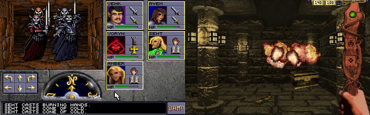
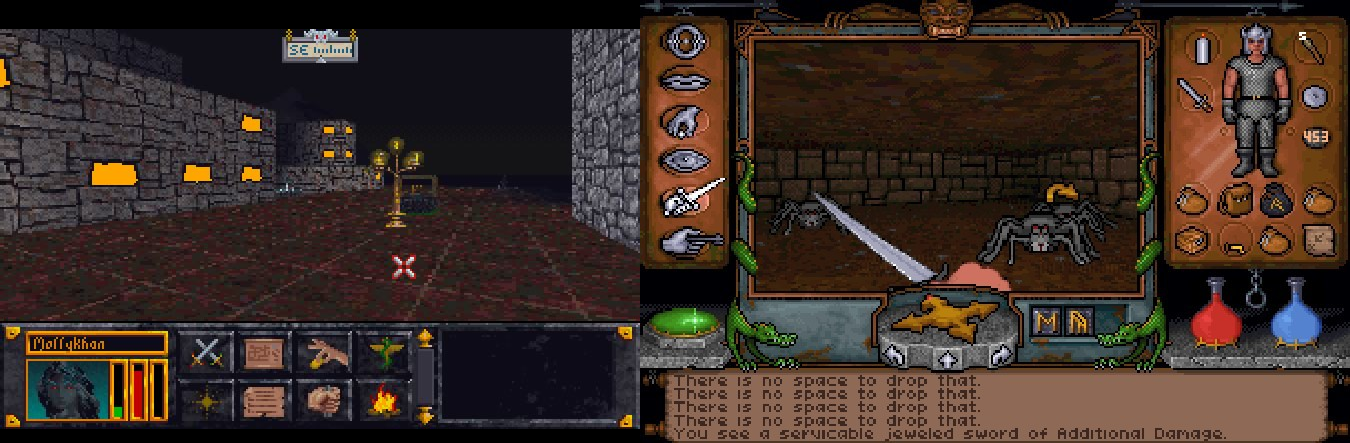
I’m of course talking about CRPGs, and one of the earlier forms of CRPGs were first person dungeon crawlers, using either 3D or traditional 2D graphics.
As a game designer, I often find myself walking a tightrope of minimizing the effort needed to establish an art pipeline for a game and getting a desired aesthetic. 3D takes away the need for drawing 2D art in perspective, but adds many other complications. Still, the results are often satisfying.
Setting up
For the purpose of this tutorial, the instructions will be as simple as possible. I’ll be using the GMS2 room editor, but as your scope and understanding increases, you may want (or have) to write your own tool for building 3D worlds.
You can find the companion GMS2 project for this tutorial here (.zip). I will be referring to this project throughout the tutorial.
I’m going to assume you’re familiar with the room editor, so the parts I will focus on are the scripts and functions needed to convert a collection of 2D data to a format usable in 3D and the process of rendering it as a 3D scene. In this case, we’ll be working with a ds_grid converted from tiles that can be placed in the room editor.
Converting placed tiles to a grid
I am including this because not all users are familiar with tiles – if you’d like to write your own method of gathering data on where to make world geometry, feel free to skip this part.
/// @func layer_tilemap_to_grid
/// @desc {void} takes a given tile layer and populates a given ds_grid with a given value
/// @arg {string} layerName
/// @arg {grid} grid
/// @arg {any} value

var _layerName = argument[0];
var _grid = argument[1];
var _value = argument[2];

var _layer = layer_get_id(_layerName);
var _tileMap = layer_tilemap_get_id(_layer);

var _width = ds_grid_width(_grid)
var _height = ds_grid_height(_grid)

var _tile = -1;

for (var _y = 0; _y < _height ; _y++){
   for (var _x = 0; _x < _width; _x++){
      _tile = tilemap_get(_tileMap, _x, _y);
      if (_tile == 1){
         _grid[# _x, _y] = _value;
      }
   }
}
This goes through a grid loop and checks to see if a tile of index 1 exists at a given position on the tilemap, then sets that position in a companion grid. Grids are easier to access than tilemaps and there are many places in the example project where grid checks are performed.
Now that we have our data in grid format, let’s move on to the interesting stuff.
Overview: understanding the 3D pipeline
In order to build our world and render it on screen, we need to do a few things:
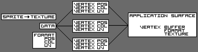
1) Define a vertex format
The vertex format needs to be defined first, setting the rules of how the buffer is constructed and rendered.
2) Build a vertex buffer
A vertex buffer is the collection of vertex data – it is where we build our world.
3) Set a texture
Setting the texture specifies the image mapped to geometry, but it’s not the same thing as a sprite asset. Textures are defined in code using sprite_get_texture(sprite_index, image_index). The texture can be made up of many images of varying sizes, but we’ll talk a bit about how textures are mapped onto geometry later.
4) Submit the vertex buffer
Finally, a vertex buffer can be rendered using vertex_submit(vertex buffer, primitive type, texture), either in a surface or a draw event. When submitting the vertex buffer, a texture should be specified unless you opt to only use a vertex color instead. In that case, you can safely pass in -1 as the texture.
Now, let’s get into the details of each step.
Defining a vertex format
A vertex format determines how the vertex buffer is built and interpreted by the renderer. It needs position and color data at minimum, but texcoords are required if you want to display textures over geometry. Vertex formats can be defined at any time before you start to build the vertex buffer, so I put mine in the create event of a controller object.
vertex_format_begin();
vertex_format_add_position_3d();
vertex_format_add_texcoord();
vertex_format_add_colour();
world_format = vertex_format_end();
Building a vertex buffer (from a grid)
This is the fun part! We need to iterate over a grid once to build each cell of our grid into world geometry.
for (var _gridY = 0; _gridY < world_height; _gridY++){
	for (var _gridX = 0; _gridX < world_width; _gridX++){
		world_build_cell(_gridX, _gridY);
	}
}
world_build_cell(_gridX, _gridY);
for (var _i = 0; _i < __WALL.SIZE; _i++){
	var _empty = global.world_grid[# _gridX, _gridY] == __CELL.EMPTY;
	if (_empty){
		world_build_wall(_gridX, _gridY, _i);
	}
}
This is where we build the actual geometry. For each cell, we need to build up to six walls, so we loop through the size of our wall enum(0-5) and send that value in.
From now on, when we’re talking about geometry, we’ll use the floor as our example, because it is the easiest to understand. If you compare it with the other wall building code in the sample project, you may notice some patterns. If you do not conform to these patterns when building geometry, you will get culling and texture errors on render.
First we’ll look at the geometry:
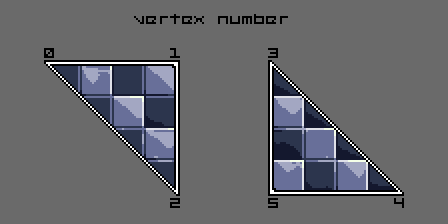
// Tri 1
vertex_position_3d(world_vbuff, _x, _y, _z); // Top Left
vertex_position_3d(world_vbuff, _x2, _y, _z); // Top Right
vertex_position_3d(world_vbuff, _x2, _y2, _z); // Bot Right
// Tri 2
vertex_position_3d(world_vbuff, _x, _y, _z); // Top Left Again
vertex_position_3d(world_vbuff, _x2, _y2, _z); // Bot Right Again
vertex_position_3d(world_vbuff, _x, _y2, _z); // Bot Left
The order triangles are built in does not matter, but the order their vertices are built in does. The cullmode we use for this project is anti-clockwise, so all triangles built clockwise will render from the “front”, and all triangles built anti-clockwise will render from the “back”.
As an alternative to manually defining all six walls, it is also possible to build two triangles six times and rotate each pair, but that is outside the scope of this tutorial.
When building these triangles, we have to populate the vertex data in accordance with the format, so you can’t just list out all of the geometry and then all of the color data – it makes for some messy code.
vertex_position_3d(world_vbuff, _x, _y, _z);
vertex_texcoord(world_vbuff, texcoord_floor_u, texcoord_floor_v);
vertex_colour(world_vbuff, _colour, 1);
You need all three of these functions to properly build in the provided format. vertex_colour is simply telling the renderer to render that vertex at 100% alpha and 100% brightness with no hue changes. But what about vertex_texcoord?
Setting up texture coordinates
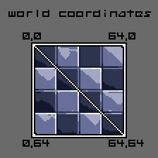
Texcoords are another type of coordinate system, this time normalised (0 through 1). A texcoord can be understood as the coordinate pair on a texture where a particular image starts or stops. You can use these to perfectly align textures or stretch and squash them.
Using the example texture for this tutorial, you can see these coordinates are y-down. This might take some getting used to if you’ve ever spent any time reading middle school math textbooks. Coincidentally, GameMaker is also y-down.
Texcoords are labeled with u and v. u,v is analogous to x,y.
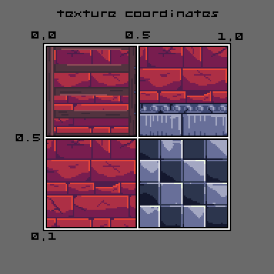
If we place four images on our sprite for use as our texture, then we need to remember where each image begins. I do the following for quick reference but it isn’t necessary.
texcoord_size = 0.5; // normalised space all our sprites take up on our texture
texcoord_wall_u = 0.5;
texcoord_wall_v = 0;
texcoord_floor_u = 0.5;
texcoord_floor_v = 0.5;
texcoord_ceiling_u = 0;
texcoord_ceiling_v = 0;
These coordinates are inserted into the vertex buffer after our position data, but for the sake of clarity, I have removed all other vertex functions from this example.
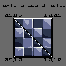
// Tri 1
vertex_texcoord(world_vbuff, texcoord_floor_u, texcoord_floor_v);
vertex_texcoord(world_vbuff, texcoord_floor_u + texcoord_size, texcoord_floor_v);
vertex_texcoord(world_vbuff, texcoord_floor_u + texcoord_size, texcoord_floor_v + texcoord_size);
// Tri 2
vertex_texcoord(world_vbuff, texcoord_floor_u, texcoord_floor_v);
vertex_texcoord(world_vbuff, texcoord_floor_u + texcoord_size, texcoord_floor_v + texcoord_size);
vertex_texcoord(world_vbuff, texcoord_floor_u, texcoord_floor_v + texcoord_size);
Setting up a view and projection matrix
Before we can render anything on screen, we need to tell the renderer how to approach the scene. The default render style in GameMaker is a 2D top-down orthographic view: there is no perspective involved in this type of view, so we’ll need to set that up.
Many of the topics I’ve covered in this tutorial could have an entire book written about them, and this step is no exception. Because only a very simple camera is necessary, I will be providing some code as-is and very briefly explaining what values are for what. If you would like to learn more about projection matrices view the resources at the bottom of this tutorial.
In GameMaker, the render matrix variables (view, projection and world) directly affect the application surface – no need for messy camera or view setups! If I say “camera” or “view” from now on, I am speaking in general terms, not about GameMaker specific tools.
var _camX = _playerX;
var _camY = _playerY;
var _camZ = _playerZ;
var _camDX = dcos(_playerDir);
var _camDY = -dsin(_playerDir);
matrix_set(matrix_view, matrix_build_lookat(_camX, _camY, _camZ, _camX + _camDX, _camY + _camDY, _camZ, 0, 0, 1));
You can think of the view matrix (matrix_view) as the position of a camera. The arguments are divided into three sets: From [X,Y,Z], To [X,Y,Z], and Up [X,Y,Z]. Because we are rendering a Z-up world in this example, the third set of arguments, Up, is [0,0,1]. It is also common to have a Y-up world, using [0,1,0] instead.
The From and To arguments can be identical, except if you want to rotate your camera; in that case, you’ll need to add a normalised value (-1 through 1) to the To position.
matrix_set(matrix_projection, matrix_build_projection_perspective_fov(90, room_width / room_height, 1, 2000));
If the view matrix is the camera property representing its position, then the projection matrix is the camera property representing its lens. The first argument is FOV, the next our aspect ratio (4:3), and finally the near and far clip. The near clip is where the rendering starts, and the far clip is where the rendering stops, in relation to the camera position. Near clip should be a positive non-zero value or you will have depth sorting issues. Far clip can be whatever you like.
Rendering the world
So far this has been a lot of setup with no payoff, so let’s fix that! After you’ve converted your data to be readable, built geometry from it, and set up your matrices, it is time for the moment of truth… In a surface or draw event of your choosing, submit your vertex buffer!
vertex_submit(world_vbuff, pr_trianglelist, world_texture);
Take note of the restriction of 1 texture per buffer – the reason why all images have to be on the same texture should make more sense now. You can render as many buffers as your GPU can handle, but you should still try to avoid quadratic loops and rendering each cell as its own buffer.
If you look over the source code, you’ll see a lot of little details get added in here and there, render fog being one of them. Check it out and experiment with adding more complex features!
Resources
This stuff is miles deep, but for the most basic applications, you won’t need to read any of it.
Bronze Box repo, may be updated in the future
https://github.com/cicadian/Bronze-Box/
Basically everything you need to be a (3D) professional video game developer cosplayer
https://learnopengl.com/
https://www.scratchapixel.com/lessons/mathematics-physics-for-computer-graphics/geometry
3D Projection
https://en.wikipedia.org/wiki/3D_projection
https://www.scratchapixel.com/lessons/3D-basic-rendering/rendering-3D-scene-overview/perspective-projection
Rotation of geometry
https://learnopengl.com/Getting-started/Transformations
https://en.wikipedia.org/wiki/Rotation_matrix
Therapy for later when you want to learn lighting and model importing
https://www.google.com/search?&q=pictures+of+cats
twitter.com/jujuadams